Femoral Neck Osteotomy: A Four-Guide System and What One of Them Taught Us
- Isabelle Têcheur
- 4 hours ago
- 3 min read


The femoral neck concentrates several specific anatomical constraints in a restricted space: three-dimensional geometry that varies from one patient to the next, proximity of the femoral head vasculature, and simultaneous management of the greater trochanter. 3D planning makes it possible to break the procedure down into verifiable steps, each translated into a guide adapted to the patient's anatomy.
This case required four patient-specific guides. Three were deployed intraoperatively. The fourth was not. The reason it could not be is as instructive as everything that worked.
The Central Constraint
Once the osteotomy is complete, the femoral head fragment no longer has a fixed orientation relative to the shaft. The entire guide sequence was built around this constraint.
Guide Sequence for Femoral Neck Osteotomy
The correction was planned from the patient's CT imaging, with iterative definition of the osteotomy geometry, screw positions, and fixation construct.
One of the critical planning constraints was to ensure that the posterior aspect of the femoral head and neck remained flush after reduction. The femoral artery runs just posterior to the femoral neck: any residual bony prominence at that level creates a direct vascular risk.
During the design review, Dr. Sankar identified a specific risk: once the cutting guide bridges were sectioned, the femoral head would become mobile before any stabilizing element was in place. He proposed completing 95% of each cut before sectioning the bridges, then applying a clamp before finishing. This approach was integrated into the operative protocol.
The screw guide is placed first, before any cut. It carries three K-wire channels drilled to the osteotomy line and stopped there. With the femoral head still attached to the neck, the anatomical reference is complete. After reduction, the K-wires are simply advanced to their final depth.
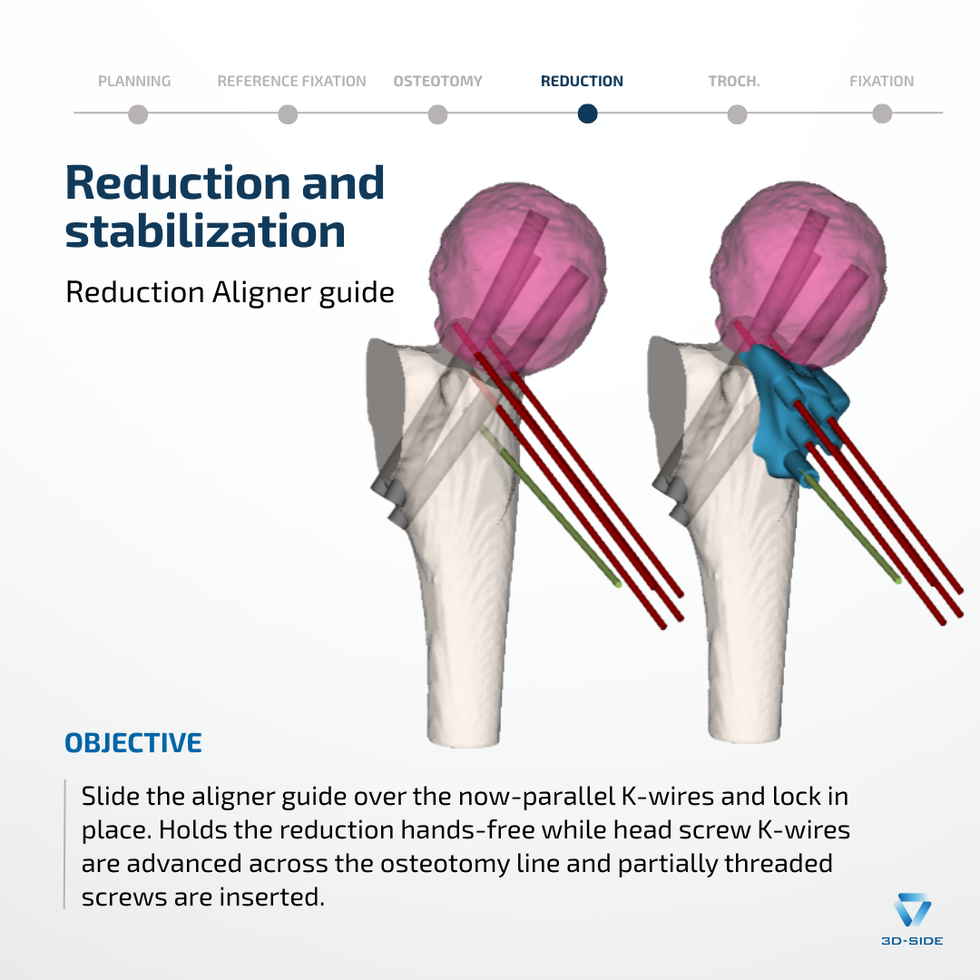
The cutting guide constrains both resection planes simultaneously, ensuring the planned amount of reduction is achieved precisely as defined preoperatively. It is held by one fixation K-wire and four aligning K-wires. After the guide is removed, the aligning K-wires remain in place: inserted divergent, they become parallel precisely when the femoral head reaches its planned postoperative position, a direct geometric signal that the correction has been achieved.
The aligner guide slides over these parallel K-wires and locks in place, holding the correction hands-free during screw insertion. Three 5.5 mm partially threaded screws provide definitive fixation (70 mm, 80 mm, 77 mm).
The Fourth Guide
A fourth guide was designed to direct fixation of the greater trochanter: bone-matched to the trochanteric apophysis, with K-wire trajectories conforming to the plan. It was manufactured, sterilized, and available on the table.
Intraoperatively, the muscular envelope blocked the access angle required for its positioning: the available soft tissue window was incompatible with the guide's approach geometry, an incompatibility not detectable in the virtual environment.
Fixation was performed freehand, using the screw trajectories and reduction targets documented in the preoperative report. Three 3.5 mm cannulated screws were placed at 43 mm, 32 mm, and 42 mm. Dr. Sankar reported finding the planned trajectories useful as a spatial reference.
Six-Week Outcome
Satisfactory clinical and radiographic progress at six weeks. Longer follow-up is needed to assess durability of correction.
“The case went great! The models and guides delivered exactly on our plan.”
Dr. Wudbhav Sankar
We thank Dr. Wudbhav Sankar for his engagement throughout the design process and for sharing this case.


Comments